 Parallel Views Inspector
Parallel Views InspectorManages viewpoints defined by a camera, a target or a focal length. Each viewpoint is considered to be an independent document with its own parameters, which can receive its own environment.
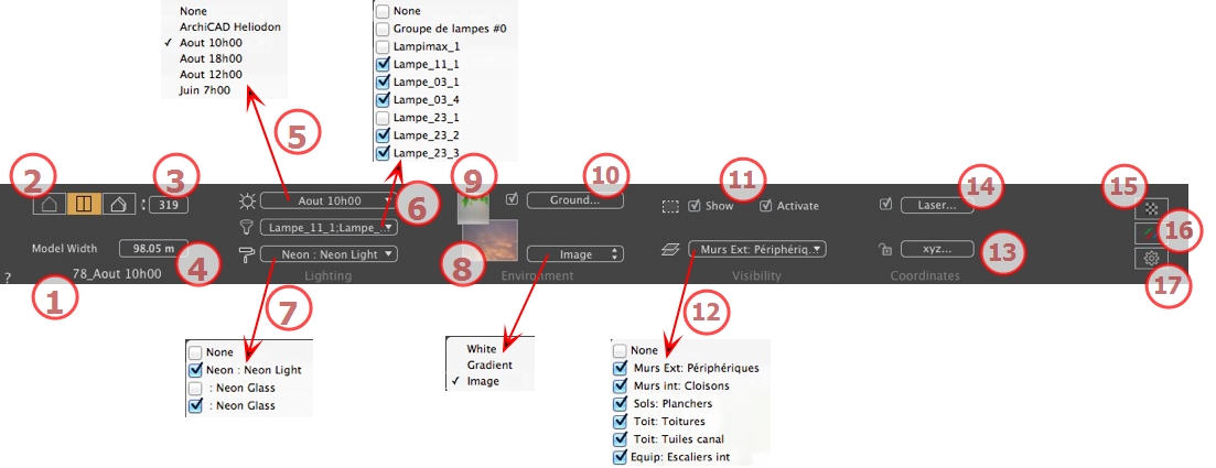
The name of the current view is displayed; double click on it to edit it.
Pivots the camera laterally. Enter a value in degrees in the related field (available only in Top View).
Defines the width of the selected view (current unit).
 NB: Value modification depends on the Viewpoint Update Mode settings in Preferences.
Links a heliodon to the view. Selecting "None" deactivates the heliodon.
Links one or more light groups to the view. Selecting "None" deactivates the light groups.
Links one or more Neon Shaders to the view. Selecting "None" deactivates the lighting.
Place a 2D, 3D or HDR Image in the Background or just drag and drop it on the relevant button. Double clicking on a button displays the editor.
The pop-up menu can be used to toggle between different types of background: Heliodon Sky, Gradient and Image.
Place a 2D image with an alpha mask on the Foreground or just drag and drop it on the relevant button. Double clicking on the button displays the editor.
To define an infinite ground per view:
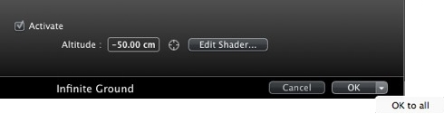
Checking/unchecking activates and deactivates the ground. The ground receives Shadows, Shaders and Objects.
Enter a value into the related field or determine the altitude graphically in Preview or in 2D View:
In Preview, click on the Altitude tool  then in the Preview, click on the scene element to define the height of the ground.
In 2D View, click on the Altitude tool then in an elevation of the 2D View, click on the geometry to define the height of the ground.
Edit Shaders activates the Shader edit mode.
OK menu: OK to all allows you to propagate the settings to all the other infinite grounds set in the project.
Clipping planes defined in the 2D View.
When checked, the box is visible in 2D View.
When checked, the clipping box takes effect in the Preview window.
Check them in the drop-down menu.
Clicking on the xyz... button opens the coordinates dialog.
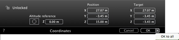
Padlock: Click on the icon to lock or unlock the coordinates.
Camera position: X, Y and Z positions
Target position: X, Y and Z positions
Allows you to limit a camera's target to an object's movement. In Object mode, right-click on an object and select "Define As Target" in the drop-down menu. Then, in Perspectives mode, select the name of the object in question in this menu.
Altitude reference: Allows you to define a position in reference to a clicked geometry.
Defines a virtual line in the project and uses it to align objects, lamps and textures.
Sets the tone for the current view.
Applies effects to the current viewpoint. The effects combine with the parameters set in the inspector.
Prepares the document for the final rendering.
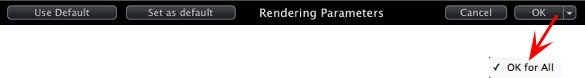
Use the default settings
Defines the current settings as the default settings.
Applies these settings to all other views for the inspector concerned.
 Example
|
Artlantis User Guide:Parallel Views Inspector |
|
© 2016 Abvent www.artlantis.com |