 2D View Window
This is used for viewing and editing the project in the following projected view:
Displays one of the following five projected views at one time: Top, Front, Right, Left or Back.
View display is independent of the current inspector.
Example: In the Perspectives inspector, you can edit lights in 2D View without activating the Lights inspector.
Right clicking on the element you wish to edit displays a pop-up menu for the current operations: Duplicate, Delete, Attribute To, etc. These are performed in real time in the Preview window and in the relevant inspectors.
From left to right: Top, Front, Right, Left or Back.
From left to right:
 Resets the camera to the position defined when the view has been activated.
 Moves the camera (the zone defined by a rectangle); Alt+Zoom to move backwards.
 Pans the scene by moving the current camera.
 Optimizes the display of the whole geometry in the view.
Clicking on this button  clips the geometry placed just before the position of the current preview camera opposite to its direction.
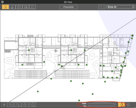
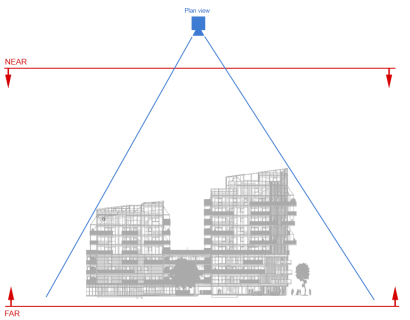
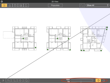
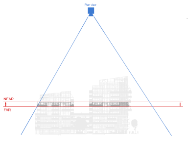
You can adjust the Far and Near clipping plane using the sliders.
The Near plane allows you to clip the geometry between the observer and the current camera position.
The Far plane allows you to clip the geometry behind the current camera position.
For example you can use the Far and Near plane to isolate one level of a multi-storey building.
;
; 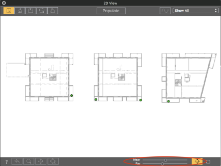
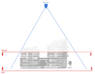
 When the Near / Far option is active, the check box becomes clickable and allows you to split the entire scene or just the geometry leaving the cameras, lamps, or objects visible in the 2D view.
 NB :The clipping plane cannot be customized: it depends on the position of the camera. Clipping does not affect the display in the Preview.
To improve visibility of the scene.
Displays all the current viewpoints, objects and lights.
Displays objects or lights having the same entity.
Displays only the selected element: point of view, object or light. The other elements are hidden.
![]() : In animation mode, this is used to create or modify a path relative to a camera, a light or an
: In animation mode, this is used to create or modify a path relative to a camera, a light or an  object.
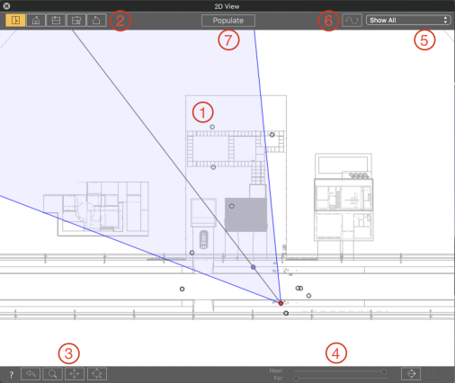
Click in the « Populate » button to display the Populate tools palette and activate the Object inspector.
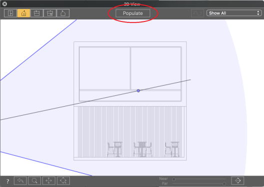
Click on the "populate tool " to display the toolbar and activate the Objects inspector.
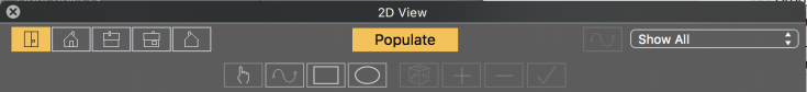
There are 4 tools to populate the scene: « Drop-Drop », Path, Rectangle and Oval.
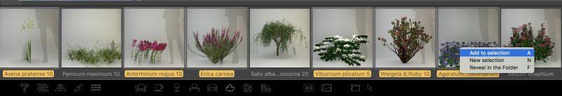
First select the objects to be spread:
- In the catalog, select a category or a sub-category, objects will be randomly chosen to be spread from this selected category
- If you select some of the items in the selected category, only those will be spread.
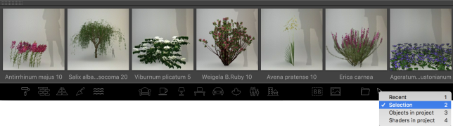
- You can also create a selection of objects from different categories and select the sub-category « Selection » :
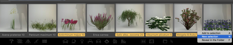
Objects will be randomly chosen from the « Selection » category.
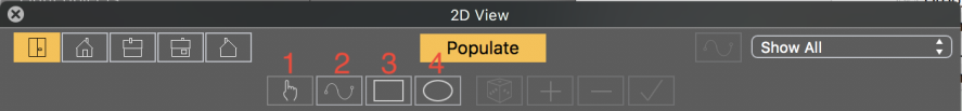
1. 'DROP-DROP'
Allows you to spread objects one by one in the 2D View.
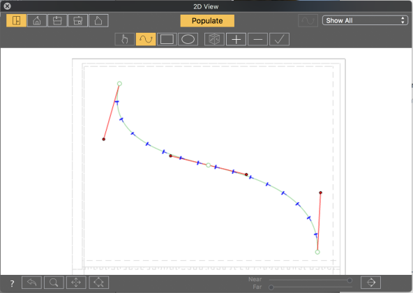
2. Path Tool
Allows you to spread objects along a path
To define the path, click in the 2D view hold the mouse down and drag to define the end of the path.
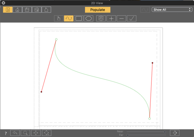
Adjust the path curve using the red handles.
Right click on the path to display the contextual menu to add/remove control points, enable random spread, lock/unlock a tangent or Open/Close the path.
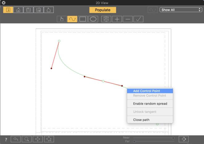
Click on the ‘+’ or ‘-‘ buttons to add or remove objects along the path.
Validate by clicking on the  button or the Enter key.
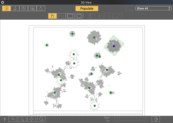
3. "RECTANGLE" & "OVALE" TOOLS
The tools  &
&  work the same way.
They allow you to spread objects within a rectangular or oval zone
To create the zone, click in the 2D view, hold the mouse down and drag to define the shape.
Once define, it can be resized using the green and red squares, it can be rotated using the yellow dots.
Then click on the ‘+’ or ‘-‘ buttons to add or remove objects in the zone and clicking on the  button.
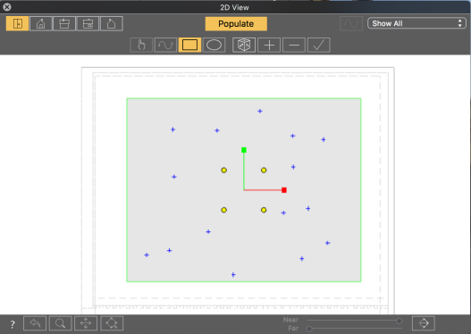
Click on  to randomly modify the distribution of the blue cross within the zone.
Then validate to create the objects by clicking on the button.
|
Artlantis User Guide:2D View Window |
|
© 2020 Abvent www.artlantis.com |